


In this beginner-friendly tutorial, we'll dive into the fundamentals of Arduino programming and circuitry by learning how to light up LEDs. We'll start with a single LED and gradually progress to building a simple traffic light system using the versatile Arduino microcontroller.
Blinking a Single LED
Materials Needed:
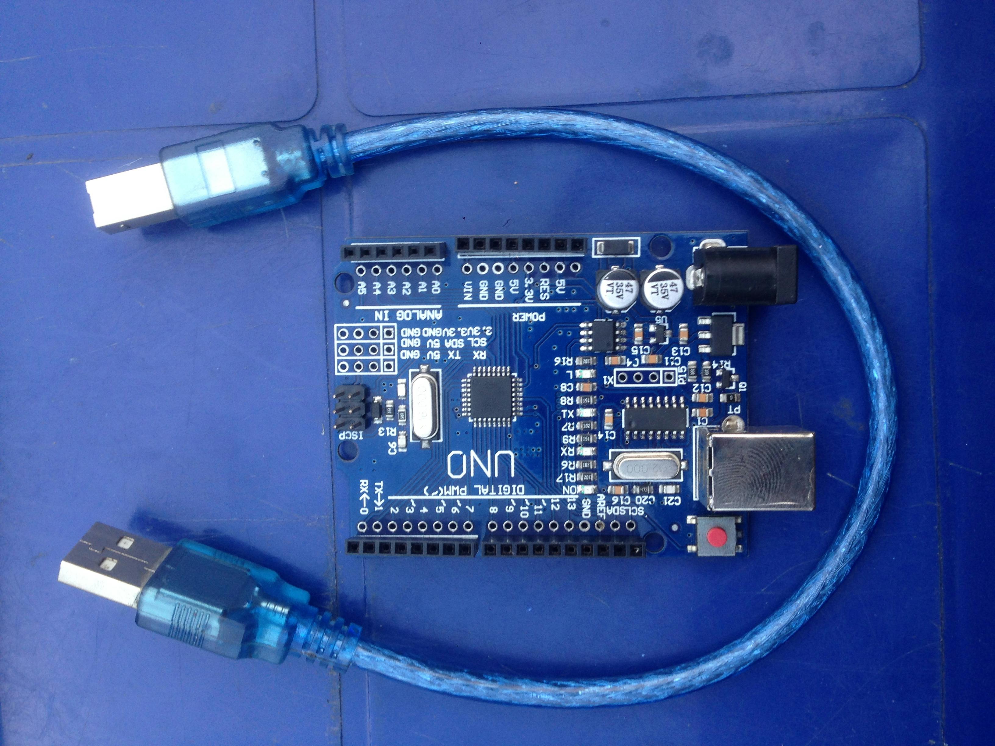
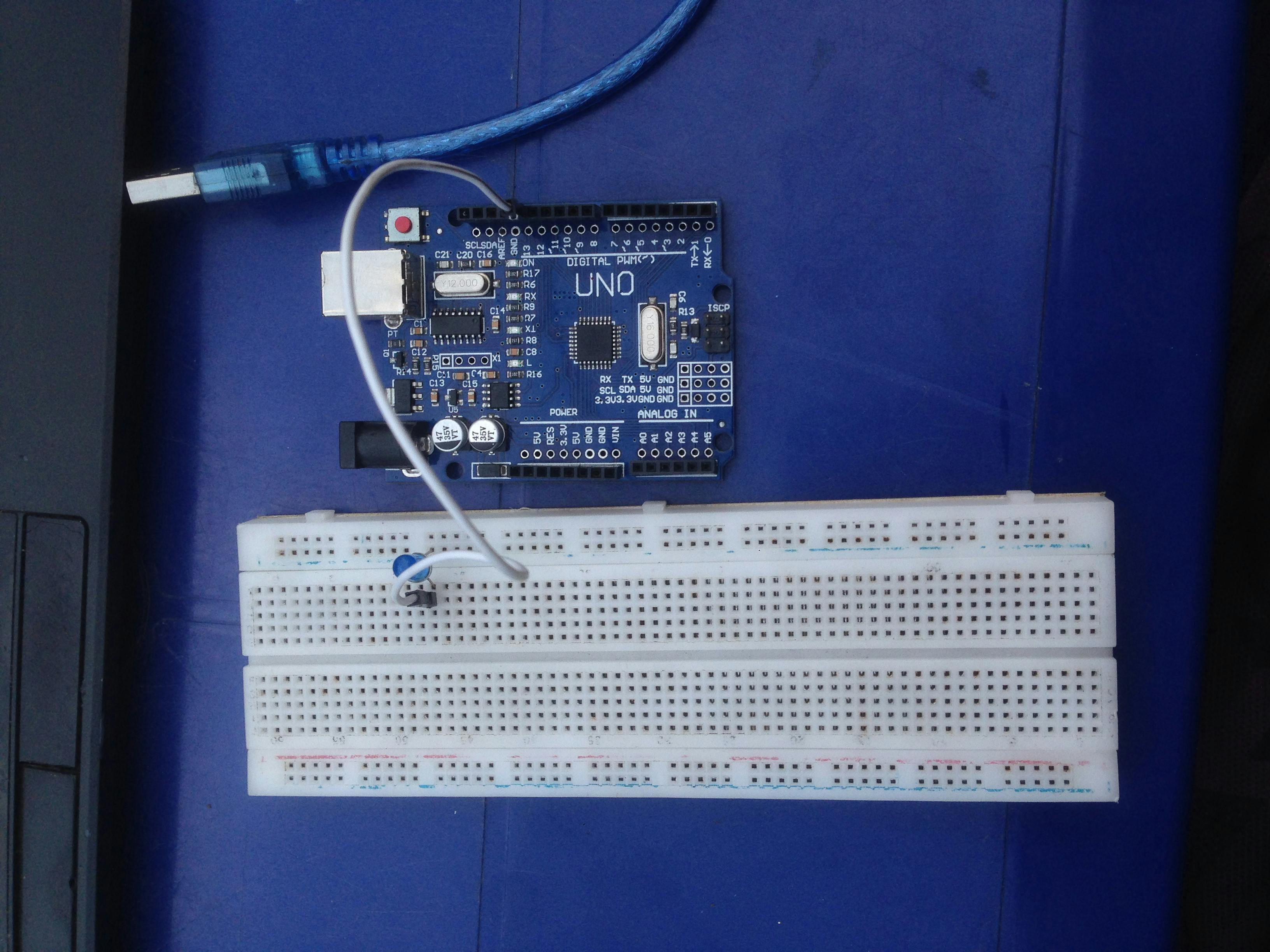
Arduino board (e.g., Arduino Uno)
Breadboard
LED (any color)
Jumper wires


Wiring Connections:
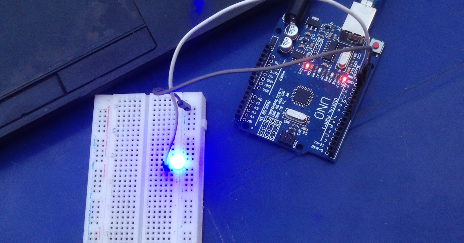
Connect the longer leg (anode) of the LED to digital pin 13 on the Arduino.
Connect the shorter leg (cathode) of the LED to the ground (GND) on the Arduino.
Power up the Arduino board.


Arduino Sketch:
void setup() {
pinMode(13, OUTPUT); // Set digital pin 13 as an output
}
void loop() {
digitalWrite(13, HIGH); // Turn on the LED
delay(1000); // Wait for 1 second
digitalWrite(13, LOW); // Turn off the LED
delay(1000); // Wait for 1 second
}
Explanation: This simple code uses the built-in LED on the Arduino board to blink at a 1-second interval. The digitalWrite function is used to turn the LED on and off.
Controlling Multiple LEDs
Now that we've mastered a single LED, let's move on to controlling multiple LEDs. We'll create a circuit with three LEDs, each lighting up in sequence.
Additional Materials Needed:
Two extra LEDs
Two 220-ohm resistors

Wiring Connections:
Connect the longer leg of the first LED to digital pin 9 on the Arduino through a 220-ohm resistor.
Connect the shorter leg of the first LED to ground (GND) on the Arduino.
Repeat steps 1 and 2 for the other two LEDs, connecting them to digital pins 10 and 11.
Arduino Sketch
void setup() {
pinMode(9, OUTPUT);
pinMode(10, OUTPUT);
pinMode(11, OUTPUT);
}
void loop() {
digitalWrite(9, HIGH); // Turn on the first LED
delay(500); // Wait for 0.5 seconds
digitalWrite(9, LOW); // Turn off the first LED
digitalWrite(10, HIGH); // Turn on the second LED
delay(500); // Wait for 0.5 seconds
digitalWrite(10, LOW); // Turn off the second LED
digitalWrite(11, HIGH); // Turn on the third LED
delay(500); // Wait for 0.5 seconds
digitalWrite(11, LOW); // Turn off the third LED
}
Explanation: This code sequentially lights up three LEDs, creating a visual sequence.
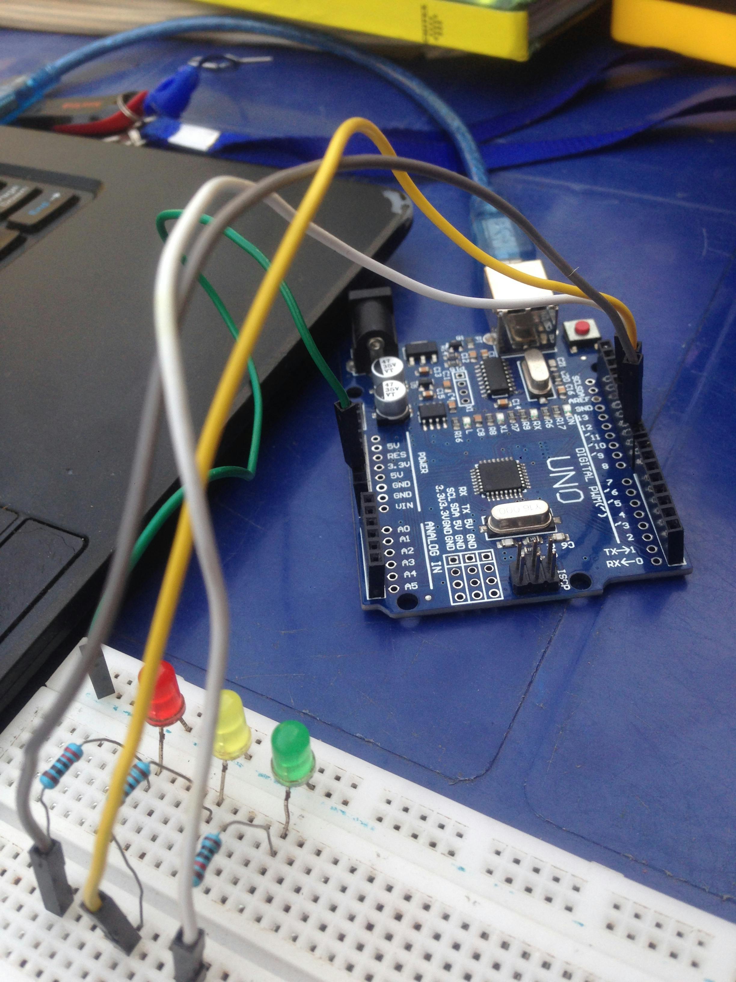
Building a Simple Traffic Light System
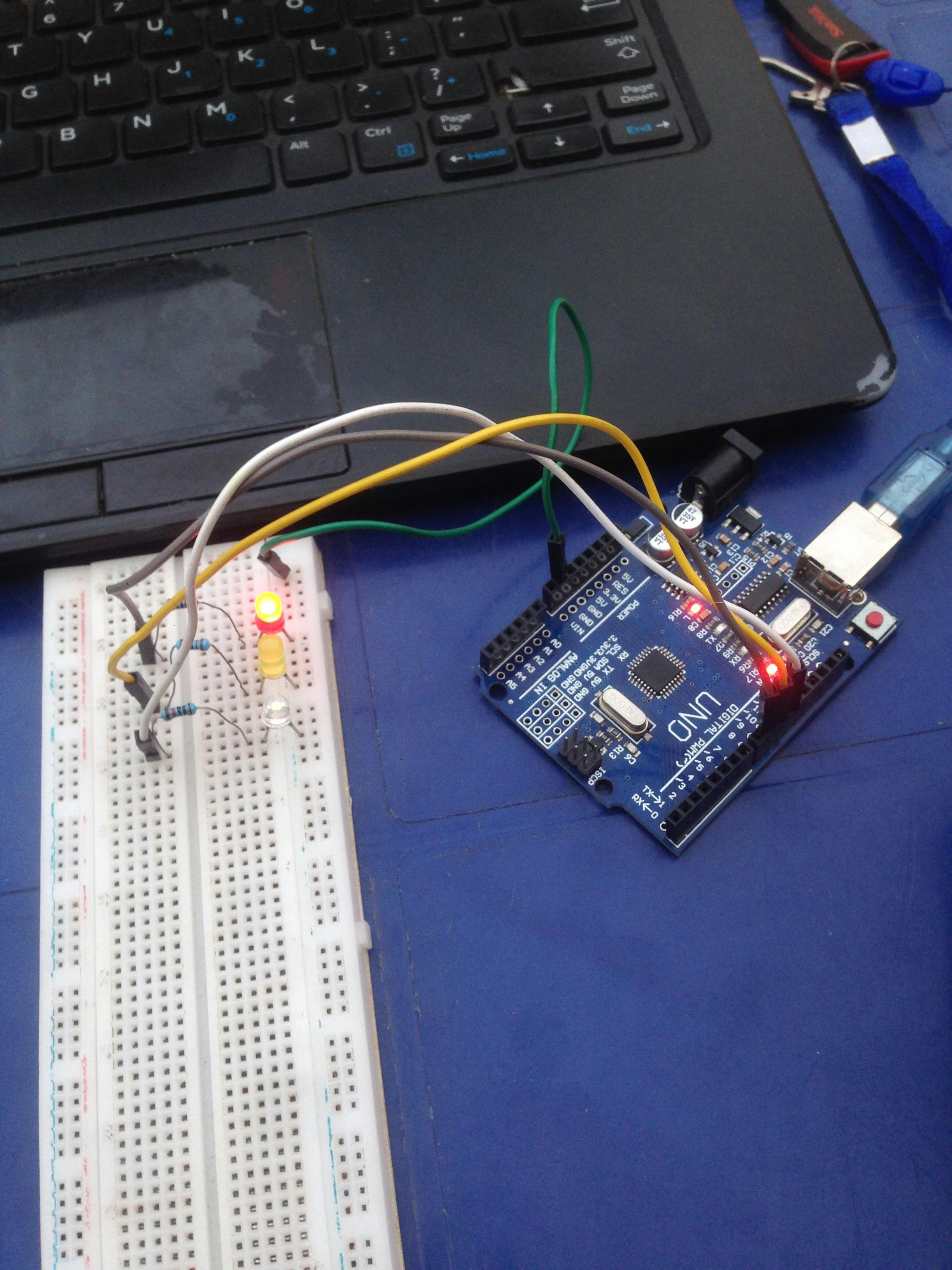
Now, let's take our LED control skills to the next level by creating a basic traffic light system with red, yellow, and green LEDs.
Additional Materials Needed:
Two extra LEDs (red and yellow)
Two 220-ohm resistors
Wiring Connections:
Connect the red LED to digital pin 9 through a 220-ohm resistor.
Connect the yellow LED to digital pin 10 through a 220-ohm resistor.
Connect the green LED to digital pin 11 through a 220-ohm resistor.

Arduino Sketch:
void setup() {
pinMode(9, OUTPUT); // Red LED
pinMode(10, OUTPUT); // Yellow LED
pinMode(11, OUTPUT); // Green LED
}
void loop() {
// Red light
digitalWrite(9, HIGH);
delay(2000);
// Red and yellow lights (transition)
digitalWrite(9, HIGH);
digitalWrite(10, HIGH);
delay(1000);
digitalWrite(9, LOW);
digitalWrite(10, LOW);
// Green light
digitalWrite(11, HIGH);
delay(2000);
// Yellow light
digitalWrite(10, HIGH);
delay(1000);
// Turn off all lights for a smooth transition to the next cycle
digitalWrite(9, LOW);
digitalWrite(10, LOW);
digitalWrite(11, LOW);
// Add a delay between cycles
delay(1000);
}
Explanation: This code simulates a basic traffic light system with the sequence of red, red-yellow transition, green, yellow, and a pause between cycles.
Conclusion: Congratulations on completing the first steps in your Arduino journey! You've learned how to control single and multiple LEDs, and even built a simple traffic light system. Stay tuned for more exciting Arduino projects and lessons on Roemai. Happy tinkering!